


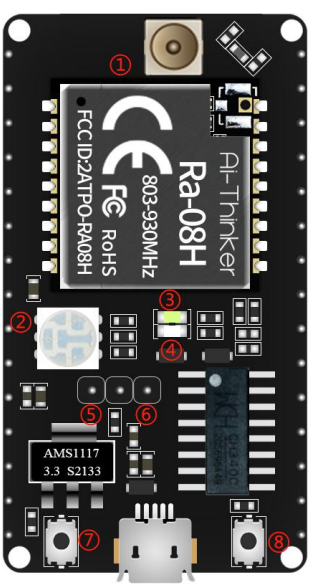
 LoRa Ra-08h modul pročitati status ulaznog pina
Preuzeo sam primere sa sajta: https://github.com/Ai-Thinker-Open/Ai-Thinker-LoRaWAN-Ra-08
Za programiranje se koristi keil uVision5 u kombinacijom sa GCC kompajlerom info:
Code:
IDE-Version:
µVision V5.37.0.0
Copyright (C) 2022 ARM Ltd and ARM Germany GmbH. All rights reserved.
License Information:
dak d
ttv
LIC=----
Tool Version Numbers:
Toolchain: MDK-Lite Version: <unknown>
Toolchain Path: C:\Program Files (x86)\GNU Arm Embedded Toolchain\9 2020-q2-update\bin
C Compiler: GCC.exe
Assembler: AS.exe
Linker/Locator: LD.exe
Librarian: AR.exe
Hex Converter: OBJCOPY.exe
CPU DLL: SARMCM3.DLL
Dialog DLL: TCM.DLL
Target DLL: Segger\JL2CM3.DLL
Dialog DLL: TCM.DLL
Alat za flešovanje bin fajla u uC: https://docs.ai-thinker.com/_media/firmware_update_tool.zip
Zna li neko kako da pročitam status sa IO8 pina i odštampam vrednos na uart?
main.c
Code:
#include <stdio.h>
#include <stdarg.h>
#include "tremo_uart.h"
#include "tremo_gpio.h"
#include "tremo_rcc.h"
#include "tremo_delay.h"
#define TEST_GPIOX GPIOA
#define TEST_PIN GPIO_PIN_4
//-----------------definicija ulaznih pinova==================
#define INGPIO8 GPIOA
#define INPUTIO8 GPIO_PIN_8
void uart_log_init(void)
{
// uart0
gpio_set_iomux(GPIOB, GPIO_PIN_0, 1);
gpio_set_iomux(GPIOB, GPIO_PIN_1, 1);
/* uart config struct init */
uart_config_t uart_config;
uart_config_init(&uart_config);
uart_config.baudrate = UART_BAUDRATE_115200;
uart_init(CONFIG_DEBUG_UART, &uart_config);
uart_cmd(CONFIG_DEBUG_UART, ENABLE);
}
int main(void)
{
rcc_enable_peripheral_clk(RCC_PERIPHERAL_UART0, true);
rcc_enable_peripheral_clk(RCC_PERIPHERAL_GPIOB, true);
rcc_enable_peripheral_clk(RCC_PERIPHERAL_GPIOA, true);
gpio_init(TEST_GPIOX, TEST_PIN, GPIO_MODE_OUTPUT_PP_HIGH);
rcc_enable_peripheral_clk(RCC_PERIPHERAL_GPIOA, true);
gpio_init(INGPIO8, INPUTIO8, GPIO_MODE_INPUT_PULL_UP);
uart_log_init();
printf("Inicijalizacija serijskog porta\r\n");
/* Infinite loop */
while (1) {
printf("hello world\r\n");
gpio_toggle(TEST_GPIOX, TEST_PIN);
delay_ms(1000);
printf("PIN8 status=");
int pera= (gpio_level_t gpio_read(gpio_t* TEST_GPIOX, uint8_t INPUTIO8));
//printf('gpio_level_t gpio_read(gpio_t* TEST_GPIOX, uint8_t INPUTIO8)');
//printf(assert_param(IS_GPIO_PIN(TEST_GPIOX, INPUTIO8)));
}
}
#ifdef USE_FULL_ASSERT
void assert_failed(void* file, uint32_t line)
{
(void)file;
(void)line;
while (1) { }
}
#endif
Ispod je sadržaj fajla "tremo_gpio.c"
Code:
#include <stdbool.h>
#include "tremo_rcc.h"
#include "tremo_gpio.h"
/**
* @brief Deinitializes the GPIO registers to the reset values
* @note This will reset all the registers of GPIOA, GPIOB, GPIOC and GPIOD
* @param None
* @retval None
*/
void gpio_deinit(void)
{
rcc_enable_peripheral_clk(RCC_PERIPHERAL_GPIOA, false);
rcc_enable_peripheral_clk(RCC_PERIPHERAL_GPIOB, false);
rcc_enable_peripheral_clk(RCC_PERIPHERAL_GPIOC, false);
rcc_enable_peripheral_clk(RCC_PERIPHERAL_GPIOD, false);
rcc_rst_peripheral(RCC_PERIPHERAL_GPIOA, true);
rcc_rst_peripheral(RCC_PERIPHERAL_GPIOA, false);
}
/**
* @brief Init the GPIOx according to the specified parameters
* @note The default mode of the gpio is GPIO_MODE_ANALOG.
* @param gpiox Select the GPIO peripheral number(GPIOA, GPIOB, GPIOC and GPIOD)
* @param gpio_pin Select the GPIO pin number.
* This parameter can be one of the following values:
* @arg GPIO_PIN_0: Pin 0
* @arg GPIO_PIN_1: Pin 1
* @arg GPIO_PIN_2: Pin 2
* @arg GPIO_PIN_3: Pin 3
* @arg GPIO_PIN_4: Pin 4
* @arg GPIO_PIN_5: Pin 5
* @arg GPIO_PIN_6: Pin 6
* @arg GPIO_PIN_7: Pin 7
* @arg GPIO_PIN_8: Pin 8
* @arg GPIO_PIN_9: Pin 9
* @arg GPIO_PIN_10: Pin 10
* @arg GPIO_PIN_11: Pin 11
* @arg GPIO_PIN_12: Pin 12
* @arg GPIO_PIN_13: Pin 13
* @arg GPIO_PIN_14: Pin 14
* @arg GPIO_PIN_15: Pin 15
* @param mode Select the GPIO mode.
* This parameter can be one of the following values:
* @arg GPIO_MODE_INPUT_FLOATING: Input floating
* @arg GPIO_MODE_INPUT_PULL_UP: Input pull-up
* @arg GPIO_MODE_INPUT_PULL_DOWN: Input pull-down
* @arg GPIO_MODE_OUTPUT_PP_HIGH: Output push-pull high level
* @arg GPIO_MODE_OUTPUT_PP_LOW: Output push-pull low level
* @arg GPIO_MODE_OUTPUT_OD_HIZ: Output open-drain high-impedance
* @arg GPIO_MODE_OUTPUT_OD_LOW: Output open-drain low level
* @arg GPIO_MODE_ANALOG: Analog
* @retval None
*/
void gpio_init(gpio_t* gpiox, uint8_t gpio_pin, gpio_mode_t mode)
{
assert_param(IS_GPIO_PIN(gpiox, gpio_pin));
assert_param(IS_GPIO_MODE(mode));
switch (mode) {
case GPIO_MODE_INPUT_FLOATING: {
gpiox->OER |= (1 << gpio_pin);
gpiox->IER |= (1 << gpio_pin);
gpiox->PER &= ~(1 << gpio_pin);
break;
}
case GPIO_MODE_INPUT_PULL_UP: {
gpiox->OER |= (1 << gpio_pin);
gpiox->IER |= (1 << gpio_pin);
gpiox->PER |= (1 << gpio_pin);
gpiox->PSR |= (1 << gpio_pin);
break;
}
case GPIO_MODE_INPUT_PULL_DOWN: {
gpiox->OER |= (1 << gpio_pin);
gpiox->IER |= (1 << gpio_pin);
gpiox->PER |= (1 << gpio_pin);
gpiox->PSR &= ~(1 << gpio_pin);
break;
}
case GPIO_MODE_OUTPUT_PP_HIGH: {
gpiox->OER &= ~(1 << gpio_pin);
gpiox->IER &= ~(1 << gpio_pin);
gpiox->OTYPER &= ~(1 << gpio_pin);
gpiox->ODR |= (1 << gpio_pin);
break;
}
case GPIO_MODE_OUTPUT_PP_LOW: {
gpiox->OER &= ~(1 << gpio_pin);
gpiox->IER &= ~(1 << gpio_pin);
gpiox->OTYPER &= ~(1 << gpio_pin);
gpiox->ODR &= ~(1 << gpio_pin);
break;
}
case GPIO_MODE_OUTPUT_OD_HIZ: {
if (gpiox == GPIOD && gpio_pin > GPIO_PIN_7) {
gpiox->ODR &= ~(1 << gpio_pin);
gpiox->IER &= ~(1 << gpio_pin);
gpiox->OER |= (1 << gpio_pin);
gpiox->PSR &= ~(1 << gpio_pin);
} else {
gpiox->OER &= ~(1 << gpio_pin);
gpiox->IER &= ~(1 << gpio_pin);
gpiox->OTYPER |= (1 << gpio_pin);
gpiox->ODR |= (1 << gpio_pin);
}
break;
}
case GPIO_MODE_OUTPUT_OD_LOW: {
if (gpiox == GPIOD && gpio_pin > GPIO_PIN_7) {
gpiox->ODR &= ~(1 << gpio_pin);
gpiox->IER &= ~(1 << gpio_pin);
gpiox->OER &= ~(1 << gpio_pin);
gpiox->PSR &= ~(1 << gpio_pin);
} else {
gpiox->OER &= ~(1 << gpio_pin);
gpiox->IER &= ~(1 << gpio_pin);
gpiox->OTYPER |= (1 << gpio_pin);
gpiox->ODR &= ~(1 << gpio_pin);
}
break;
}
default:
case GPIO_MODE_ANALOG: {
gpiox->OER |= (1 << gpio_pin);
gpiox->IER &= ~(1 << gpio_pin);
gpiox->PER &= ~(1 << gpio_pin);
break;
}
}
}
/**
* @brief Set the output level
* @param gpiox Select the GPIO peripheral number(GPIOA, GPIOB, GPIOC and GPIOD)
* @param gpio_pin Select the GPIO pin number.
* This parameter can be one of the following values:
* @arg GPIO_PIN_0: Pin 0
* @arg GPIO_PIN_1: Pin 1
* @arg GPIO_PIN_2: Pin 2
* @arg GPIO_PIN_3: Pin 3
* @arg GPIO_PIN_4: Pin 4
* @arg GPIO_PIN_5: Pin 5
* @arg GPIO_PIN_6: Pin 6
* @arg GPIO_PIN_7: Pin 7
* @arg GPIO_PIN_8: Pin 8
* @arg GPIO_PIN_9: Pin 9
* @arg GPIO_PIN_10: Pin 10
* @arg GPIO_PIN_11: Pin 11
* @arg GPIO_PIN_12: Pin 12
* @arg GPIO_PIN_13: Pin 13
* @arg GPIO_PIN_14: Pin 14
* @arg GPIO_PIN_15: Pin 15
* @param level Output level.
* This parameter can be one of the following values:
* @arg GPIO_LEVEL_HIGH: high level
* @arg GPIO_LEVEL_LOW: low level
* @retval None
*/
void gpio_write(gpio_t* gpiox, uint8_t gpio_pin, gpio_level_t level)
{
assert_param(IS_GPIO_PIN(gpiox, gpio_pin));
if (level != GPIO_LEVEL_LOW)
gpiox->BSR |= 1 << gpio_pin;
else
gpiox->BRR |= 1 << gpio_pin;
}
/**
* @brief Read the input level
* @param gpiox Select the GPIO peripheral number(GPIOA, GPIOB, GPIOC and GPIOD)
* @param gpio_pin Select the GPIO pin number.
* This parameter can be one of the following values:
* @arg GPIO_PIN_0: Pin 0
* @arg GPIO_PIN_1: Pin 1
* @arg GPIO_PIN_2: Pin 2
* @arg GPIO_PIN_3: Pin 3
* @arg GPIO_PIN_4: Pin 4
* @arg GPIO_PIN_5: Pin 5
* @arg GPIO_PIN_6: Pin 6
* @arg GPIO_PIN_7: Pin 7
* @arg GPIO_PIN_8: Pin 8
* @arg GPIO_PIN_9: Pin 9
* @arg GPIO_PIN_10: Pin 10
* @arg GPIO_PIN_11: Pin 11
* @arg GPIO_PIN_12: Pin 12
* @arg GPIO_PIN_13: Pin 13
* @arg GPIO_PIN_14: Pin 14
* @arg GPIO_PIN_15: Pin 15
* @retval GPIO_LEVEL_HIGH High level
* @retval GPIO_LEVEL_LOW Low level
*/
gpio_level_t gpio_read(gpio_t* gpiox, uint8_t gpio_pin)
{
/* Check the parameters */
assert_param(IS_GPIO_PIN(gpiox, gpio_pin));
return ((gpiox->IDR & (1 << gpio_pin)) ? GPIO_LEVEL_HIGH : GPIO_LEVEL_LOW);
}
/**
* @brief Toggle the specified GPIO pin
* @param gpiox Select the GPIO peripheral number(GPIOA, GPIOB, GPIOC and GPIOD)
* @param gpio_pin Select the GPIO pin number.
* This parameter can be one of the following values:
* @arg GPIO_PIN_0: Pin 0
* @arg GPIO_PIN_1: Pin 1
* @arg GPIO_PIN_2: Pin 2
* @arg GPIO_PIN_3: Pin 3
* @arg GPIO_PIN_4: Pin 4
* @arg GPIO_PIN_5: Pin 5
* @arg GPIO_PIN_6: Pin 6
* @arg GPIO_PIN_7: Pin 7
* @arg GPIO_PIN_8: Pin 8
* @arg GPIO_PIN_9: Pin 9
* @arg GPIO_PIN_10: Pin 10
* @arg GPIO_PIN_11: Pin 11
* @arg GPIO_PIN_12: Pin 12
* @arg GPIO_PIN_13: Pin 13
* @arg GPIO_PIN_14: Pin 14
* @arg GPIO_PIN_15: Pin 15
* @retval None
*/
void gpio_toggle(gpio_t* gpiox, uint8_t gpio_pin)
{
assert_param(IS_GPIO_PIN(gpiox, gpio_pin));
gpiox->ODR ^= (1 << gpio_pin);
}
/**
* @brief Config the output drive capability of the specified GPIO pin
* @param gpiox Select the GPIO peripheral number(GPIOA, GPIOB, GPIOC and GPIOD)
* @param gpio_pin Select the GPIO pin number.
* This parameter can be one of the following values:
* @arg GPIO_PIN_0: Pin 0
* @arg GPIO_PIN_1: Pin 1
* @arg GPIO_PIN_2: Pin 2
* @arg GPIO_PIN_3: Pin 3
* @arg GPIO_PIN_4: Pin 4
* @arg GPIO_PIN_5: Pin 5
* @arg GPIO_PIN_6: Pin 6
* @arg GPIO_PIN_7: Pin 7
* @arg GPIO_PIN_8: Pin 8
* @arg GPIO_PIN_9: Pin 9
* @arg GPIO_PIN_10: Pin 10
* @arg GPIO_PIN_11: Pin 11
* @arg GPIO_PIN_12: Pin 12
* @arg GPIO_PIN_13: Pin 13
* @arg GPIO_PIN_14: Pin 14
* @arg GPIO_PIN_15: Pin 15
* @param drive Output drive capability.
* This parameter can be one of the following values:
* @arg GPIO_DRIVE_CAPABILITY_4MA: The max current is 4mA
* @arg GPIO_DRIVE_CAPABILITY_8MA: The max current is 8mA
* @retval None
*/
void gpio_config_drive_capability(gpio_t* gpiox, uint8_t gpio_pin, gpio_drive_capability_t drive)
{
assert_param(IS_GPIO_PIN(gpiox, gpio_pin));
if (drive)
gpiox->DSR |= 1 << gpio_pin;
else
gpiox->DSR &= ~(1 << gpio_pin);
}
/**
* @brief Config the interrupt type of the specified GPIO pin
* @param gpiox Select the GPIO peripheral number(GPIOA, GPIOB, GPIOC and GPIOD)
* @param gpio_pin Select the GPIO pin number.
* This parameter can be one of the following values:
* @arg GPIO_PIN_0: Pin 0
* @arg GPIO_PIN_1: Pin 1
* @arg GPIO_PIN_2: Pin 2
* @arg GPIO_PIN_3: Pin 3
* @arg GPIO_PIN_4: Pin 4
* @arg GPIO_PIN_5: Pin 5
* @arg GPIO_PIN_6: Pin 6
* @arg GPIO_PIN_7: Pin 7
* @arg GPIO_PIN_8: Pin 8
* @arg GPIO_PIN_9: Pin 9
* @arg GPIO_PIN_10: Pin 10
* @arg GPIO_PIN_11: Pin 11
* @arg GPIO_PIN_12: Pin 12
* @arg GPIO_PIN_13: Pin 13
* @arg GPIO_PIN_14: Pin 14
* @arg GPIO_PIN_15: Pin 15
* @param intr_type The interrupt type.
* This parameter can be one of the following values:
* @arg GPIO_INTR_NONE: Disable GPIO interrupt
* @arg GPIO_INTR_RISING_EDGE: Rising edge
* @arg GPIO_INTR_FALLING_EDGE: Falling edge
* @arg GPIO_INTR_RISING_FALLING_EDGE: Both rising and falling edg
* @retval None
*/
void gpio_config_interrupt(gpio_t* gpiox, uint8_t gpio_pin, gpio_intr_t intr_type)
{
assert_param(IS_GPIO_PIN(gpiox, gpio_pin));
assert_param(IS_GPIO_INTR(intr_type));
gpio_clear_interrupt(gpiox, gpio_pin);
TREMO_REG_SET(gpiox->ICR, (0x3 << 2 * gpio_pin), (intr_type << 2 * gpio_pin));
}
/**
* @brief Clear the interrupt status of the specified GPIO pin
* @param gpiox Select the GPIO peripheral number(GPIOA, GPIOB, GPIOC and GPIOD)
* @param gpio_pin Select the GPIO pin number.
* This parameter can be one of the following values:
* @arg GPIO_PIN_0: Pin 0
* @arg GPIO_PIN_1: Pin 1
* @arg GPIO_PIN_2: Pin 2
* @arg GPIO_PIN_3: Pin 3
* @arg GPIO_PIN_4: Pin 4
* @arg GPIO_PIN_5: Pin 5
* @arg GPIO_PIN_6: Pin 6
* @arg GPIO_PIN_7: Pin 7
* @arg GPIO_PIN_8: Pin 8
* @arg GPIO_PIN_9: Pin 9
* @arg GPIO_PIN_10: Pin 10
* @arg GPIO_PIN_11: Pin 11
* @arg GPIO_PIN_12: Pin 12
* @arg GPIO_PIN_13: Pin 13
* @arg GPIO_PIN_14: Pin 14
* @arg GPIO_PIN_15: Pin 15
* @retval None
*/
void gpio_clear_interrupt(gpio_t* gpiox, uint8_t gpio_pin)
{
assert_param(IS_GPIO_PIN(gpiox, gpio_pin));
gpiox->IFR = (gpiox->IFR & 0x3 << 2 * gpio_pin);
}
/**
* @brief Get the interrupt status of the specified GPIO pin
* @param gpiox Select the GPIO peripheral number(GPIOA, GPIOB, GPIOC and GPIOD)
* @param gpio_pin Select the GPIO pin number.
* This parameter can be one of the following values:
* @arg GPIO_PIN_0: Pin 0
* @arg GPIO_PIN_1: Pin 1
* @arg GPIO_PIN_2: Pin 2
* @arg GPIO_PIN_3: Pin 3
* @arg GPIO_PIN_4: Pin 4
* @arg GPIO_PIN_5: Pin 5
* @arg GPIO_PIN_6: Pin 6
* @arg GPIO_PIN_7: Pin 7
* @arg GPIO_PIN_8: Pin 8
* @arg GPIO_PIN_9: Pin 9
* @arg GPIO_PIN_10: Pin 10
* @arg GPIO_PIN_11: Pin 11
* @arg GPIO_PIN_12: Pin 12
* @arg GPIO_PIN_13: Pin 13
* @arg GPIO_PIN_14: Pin 14
* @arg GPIO_PIN_15: Pin 15
* @retval it_status_t The interrupt status of the specified GPIO pin(SET or RESET)
*/
it_status_t gpio_get_interrupt_status(gpio_t* gpiox, uint8_t gpio_pin)
{
assert_param(IS_GPIO_PIN(gpiox, gpio_pin));
return (gpiox->IFR & (0x3 << 2 * gpio_pin)) ? SET : RESET;
}
/**
* @brief Config the wakeup setting of the specified GPIO pin
* @note This function is used to config the wakeup setting in stop0/1/2 mode
* @param gpiox Select the GPIO peripheral number(GPIOA, GPIOB, GPIOC and GPIOD)
* @param gpio_pin Select the GPIO pin number.
* This parameter can be one of the following values:
* @arg GPIO_PIN_0: Pin 0
* @arg GPIO_PIN_1: Pin 1
* @arg GPIO_PIN_2: Pin 2
* @arg GPIO_PIN_3: Pin 3
* @arg GPIO_PIN_4: Pin 4
* @arg GPIO_PIN_5: Pin 5
* @arg GPIO_PIN_6: Pin 6
* @arg GPIO_PIN_7: Pin 7
* @arg GPIO_PIN_8: Pin 8
* @arg GPIO_PIN_9: Pin 9
* @arg GPIO_PIN_10: Pin 10
* @arg GPIO_PIN_11: Pin 11
* @arg GPIO_PIN_12: Pin 12
* @arg GPIO_PIN_13: Pin 13
* @arg GPIO_PIN_14: Pin 14
* @arg GPIO_PIN_15: Pin 15
* @param enable If set to true, this gpio can wakeup the system from stop0/1/2 mode.
* @param wakeup_level Wakeup level.
* This parameter can be one of the following values:
* @arg GPIO_LEVEL_HIGH: high level
* @arg GPIO_LEVEL_LOW: low level
* @retval None
*/
void gpio_config_wakeup(gpio_t* gpiox, uint8_t gpio_pin, bool enable, gpio_level_t wakeup_level)
{
assert_param(IS_GPIO_PIN(gpiox, gpio_pin));
// stop0-2
TREMO_REG_EN(gpiox->WUCR, (1 << gpio_pin), enable);
TREMO_REG_EN(gpiox->WULVL, (1 << gpio_pin), wakeup_level > 0);
}
/**
* @brief Config the wakeup setting of the specified GPIO pin
* @note This function is used to config the wakeup setting of GPIO0-GPIO55 in stop3 mode.
* In stop3 mode, the GPIO0-GPIO55 are divided to 14 groups. Only one gpio in the group can be configed to wakeup the system at the same time.
* The following are the groups:
* - GPIOA_0/1/2/3
* - GPIOA_4/5/12/13
* - GPIOA_8/9/10/11
* - GPIOA_6/7/14/15
* - GPIOB_0/1/2/3
* - GPIOB_4/5/6/7
* - GPIOB_8/9/10/11
* - GPIOB_12/13/14/15
* - GPIOC_0/1/2/3
* - GPIOC_4/5/6/7
* - GPIOC_8/9/10/11
* - GPIOC_12/13/14/15
* - GPIOD_0/1/2/3
* - GPIOD_4/5/6/7
* @param gpiox Select the GPIO peripheral number(GPIOA, GPIOB, GPIOC and GPIOD)
* @param gpio_pin Select the GPIO pin number.
* This parameter can be one of the following values:
* @arg GPIO_PIN_0: Pin 0
* @arg GPIO_PIN_1: Pin 1
* @arg GPIO_PIN_2: Pin 2
* @arg GPIO_PIN_3: Pin 3
* @arg GPIO_PIN_4: Pin 4
* @arg GPIO_PIN_5: Pin 5
* @arg GPIO_PIN_6: Pin 6
* @arg GPIO_PIN_7: Pin 7
* @arg GPIO_PIN_8: Pin 8
* @arg GPIO_PIN_9: Pin 9
* @arg GPIO_PIN_10: Pin 10
* @arg GPIO_PIN_11: Pin 11
* @arg GPIO_PIN_12: Pin 12
* @arg GPIO_PIN_13: Pin 13
* @arg GPIO_PIN_14: Pin 14
* @arg GPIO_PIN_15: Pin 15
* @param enable If set to true, this gpio can wakeup the system from stop3 mode.
* @param wakeup_level Wakeup level.
* This parameter can be one of the following values:
* @arg GPIO_LEVEL_HIGH: high level
* @arg GPIO_LEVEL_LOW: low level
* @retval None
*/
void gpio_config_stop3_wakeup(gpio_t* gpiox, uint8_t gpio_pin, bool enable, gpio_level_t wakeup_level)
{
assert_param(IS_GPIO_PIN(gpiox, gpio_pin));
if (gpio_pin > GPIO_PIN_7 && gpiox == GPIOD)
return;
if (gpiox == GPIOA) {
if (gpio_pin == GPIO_PIN_6 || gpio_pin == GPIO_PIN_7)
gpio_pin += 6;
else if (gpio_pin == GPIO_PIN_12 || gpio_pin == GPIO_PIN_13)
gpio_pin -= 6;
}
uint32_t group = gpio_pin / 4;
uint32_t offset = gpio_pin % 4;
uint32_t tmp_mask = 0xF;
uint32_t tmp = offset | (wakeup_level ? 0x4 : 0x0) | (enable ? 0x8 : 0x0);
TREMO_REG_SET(gpiox->STOP3_WUCR, (tmp_mask << (4 * group)), (tmp << (4 * group)));
}
/**
* @brief Config iomux of the specified GPIO pin
* @param gpiox Select the GPIO peripheral number(GPIOA, GPIOB, GPIOC and GPIOD)
* @param gpio_pin Select the GPIO pin number.
* This parameter can be one of the following values:
* @arg GPIO_PIN_0: Pin 0
* @arg GPIO_PIN_1: Pin 1
* @arg GPIO_PIN_2: Pin 2
* @arg GPIO_PIN_3: Pin 3
* @arg GPIO_PIN_4: Pin 4
* @arg GPIO_PIN_5: Pin 5
* @arg GPIO_PIN_6: Pin 6
* @arg GPIO_PIN_7: Pin 7
* @arg GPIO_PIN_8: Pin 8
* @arg GPIO_PIN_9: Pin 9
* @arg GPIO_PIN_10: Pin 10
* @arg GPIO_PIN_11: Pin 11
* @arg GPIO_PIN_12: Pin 12
* @arg GPIO_PIN_13: Pin 13
* @arg GPIO_PIN_14: Pin 14
* @arg GPIO_PIN_15: Pin 15
* @param func_num The function number.
* This parameter can be one of the following values:
* @arg 0: The Function number 0, which is always GPIO function
* @arg 1: The Fucntion number 1, please refer to the IOMUX spec
* @arg 2: The Fucntion number 2, please refer to the IOMUX spec
* @arg 3: The Fucntion number 3, please refer to the IOMUX spec
* @arg 4: The Fucntion number 4, please refer to the IOMUX spec
* @arg 5: The Fucntion number 5, please refer to the IOMUX spec
* @arg 6: The Fucntion number 6, please refer to the IOMUX spec
* @arg 7: The Fucntion number 7, please refer to the IOMUX spec
* @retval None
*/
void gpio_set_iomux(gpio_t* gpiox, uint8_t gpio_pin, uint8_t func_num)
{
uint32_t tmp_mask = 0;
uint32_t tmp = 0;
assert_param(IS_GPIO_PIN(gpiox, gpio_pin));
if (gpio_pin > GPIO_PIN_7) {
uint32_t index = gpio_pin - GPIO_PIN_8;
tmp_mask = (gpiox == GPIOD) ? (0x7 << (3 * index)) : (0xF << (4 * index));
tmp = (gpiox == GPIOD) ? (func_num << (3 * index)) : (func_num << (4 * index));
TREMO_REG_SET(gpiox->AFRH, tmp_mask, tmp);
} else {
tmp_mask = (0xF << (4 * gpio_pin));
tmp = (func_num << (4 * gpio_pin));
TREMO_REG_SET(gpiox->AFRL, tmp_mask, tmp);
}
}
Plaćam ko može da mi pomogne sa ovim
pozdrav
 Re: LoRa Ra-08h modul pročitati status ulaznog pina